Home > Tech Tools > Technical Papers > The Self-Healing Affect of Metallized Capacitors
Metallized capacitors offer the advantages of volume efficiency and self-healing.
Self- healing is the ability of a metallized capacitor to clear a fault area where a momentary short occurs due to dielectric breakdown under voltage. The conditions that lead to a fault vary.
In the production of the dielectric film, contamination can occur or a process control problem can result in compromised dielectric strength. In most circumstances, these problems are isolated by the manufacturer. However there are particular dielectrics where contaminants are introduced as part of the process. Consider for example polyester. In the production of polyester, a fine particle distribution is added to the dielectric to enhance the handling characteristics. Polyester is produced as thin as 0.5- micron thickness. The particle size distribution however includes particles larger than the thickness of the film. This is one of the primary reasons that polyester film does not achieve the voltage strength of other polymers.
ECI film experience as a dielectric manufacturer enables special characterization of the dielectrics at incoming inspection. Film is sorted at the inspection process using voltage fault testing and avalanche testing. The voltage fault test requires that a predefined voltage per micron is applied to the film in a known square area for a specified period of time. The number of faults occurring during the specified time must not exceed a set amount based on the type of dielectric. The avalanche test uses the same set-up as required during the voltage fault test except there is no preset voltage level. In this test, the voltage is steadily increased until faults occur randomly and violently without ceasing.
The ability of the metallized capacitor to clear a fault is influenced by several factors. The type of dielectric influences the ability to clear. Dielectrics such as polycarbonate and polypropylene have high surface oxygen contents. This is an important factor since oxygen is necessary to vaporize or “burn-off” the electrode around the fault area. PPS is an example of a dielectric which does not have high surface oxygen content and therefore has a very low potential for self-healing.
The deposition thickness of the metallized electrode directly influences the self-healing characteristics of the capacitor. Clearing energies of 0.050-0.150 joules are typically considered the proper range for clean clearings. Energies exceeding this range can damage the layers above and below the fault point and introduce weak spots that can lead to more clearings. This affect will result in either avalanche breakdowns or very high carbon deposits. These deposits are conductive and result in poor insulation resistance (high leakage currents).
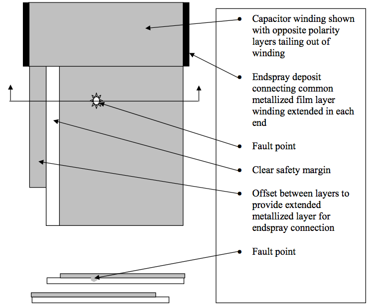
Diagram 1 – Fault point in dielectric winding

Diagram 2 – Cross section of fault point

The above diagram shows the fault point just before a clearing occurs. The dielectric strength at this point is compromised as a thin spot, pin-hole or contaminant. The clearing occurs when the voltage exceeds the insulation strength at this point and a partial discharge breaks through in a momentary short. ECI applies over voltage potential in excess of the rated voltage of the capacitor a minimum of twice during the capacitor production. The first stage is applied while the capacitor is an open (unencapsulated) section in the pretest step so that the gases produced during the clearing can escape. This first voltage application is typically the highest the unit will see so that subsequent voltages will not create new large clearings. ECI employs step down voltage testing such that no voltage applied after the unit is encapsulated exceeds the pretest voltage.
For high reliability designs, ECI uses a burn-in procedure. Voltage strength of the dielectric is directly related to temperature. By elevating the temperature of the capacitor to the maximum operating voltage and then exceeding the voltage rating at this temperature, fault points are more susceptible to breakdown. The burn-in procedure is applied typically twice. If a final burn-in is required for the capacitor a pretest burn-in is also employed to once again clear the faults before encapsulating the units.
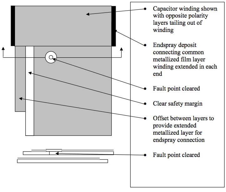
Diagram 3 – Cleared fault point in dielectric winding

Diagram 4 – Cross section of cleared fault point

The above diagram shows the fault point after a successful clearing has occurred. The dielectric breakdown at the weakest point allows an energy rush to vaporize the metallized electrode around the clearing. The diameter of the vaporized ring around the fault is proportional to the voltage applied. The vaporized electrode and byproducts of the dielectric at this point produce several gases including carbon monoxide and carbon dioxide. The pretest clearings as an open section allow these gases to escape. In finished units small clearings do not produce enough gases to damage the capacitor performance. If the larger clearings are not produced while the capacitor is in an open state, they can damage the performance. Since the gases are carbon compounds, if they do not escape the system they eventually can redeposit and lead to leakage paths through the dielectric and lower the insulation resistance of the unit.
ECI takes this process one step further. The larger gross clearings of the faults in the dielectric are cleared from the film in the conversion of the metallized dielectric to winding rolls used to produce the capacitors. In this process, the slitting equipment is specially equipped with power supplies such that any fault points are cleared in the open sheet passing between to opposing polarity metal rollers. This allows the large clearings to vaporize the metallization around the fault in open air. This step enhances the characteristics of the wound capacitors because the carbon containing gases are directly vented to the atmosphere and do not have the opportunity to redeposit the conductive carbon deposits.
In the end application of the finished capacitors, the self-healing mechanism is meant to provide a safeguard against permanent shorting. Shorts in the end application typically are the result of operating conditions not accounted for in the design of the units or by misapplication, provided the proper manufacturing steps as described above are used. For example, high voltage transients in excess of the rated dielectric withstanding voltage (DWV) of the unit will stimulate fault points. These fault points if excessive will result in high carbon deposits producing leakage paths or in damage to dielectric layers above and below the clearing, which can lead to avalanche.
Another common way to produce shorts in finished units without exceeding the DWV rating is excessive core (geometric center hot spot) temperature. Capacitors are rated for a maximum operating temperature that is relative to the core. The current ratings of the units are predicated on heat generation under power as a differential to the operating ambient. A capacitor rated for 50 ARMS at 800C with a maximum operating temperature of 1050C will have a 250C temperature rise in the core. If the capacitor is operated with 60 ARMS or at 900C, the core temperature of the capacitor will exceed the maximum operating temperature. The excessive temperature will lead to decreased voltage strength and eventual voltage breakdown and shorting. For this reason all life testing performed to rate the capacitors life expectancy is performed at the maximum operating temperature of the dielectric and over voltage conditions.
J. Bond
June 2005


