Home > Tech Tools > Technical Papers > AC Film Capacitors for Inverter Output Filters

This presentation discusses AC filter capacitors used in inverter outputs. Notably the presentation concentrates on the use of metallized polypropylene capacitors of dry construction. Oil filled capacitors dominate these applications in the higher voltage and power markets generally in front-end filtering and power factor correction. However, the use of dry capacitors for inverter output filtering has increased in the medium voltage filters over the last ten years. Switching ripple and harmonic currents superimposed on the fundamental frequency create a broad current spectrum. Dry film capacitors are excellently suited to these applications. This presentation examines typical application requirements, sample heating calculations, and life projection. The self-healing mechanism is explained to show how this desirable aspect can be the path to catastrophic failure, and the safety mechanisms developed by ECI.
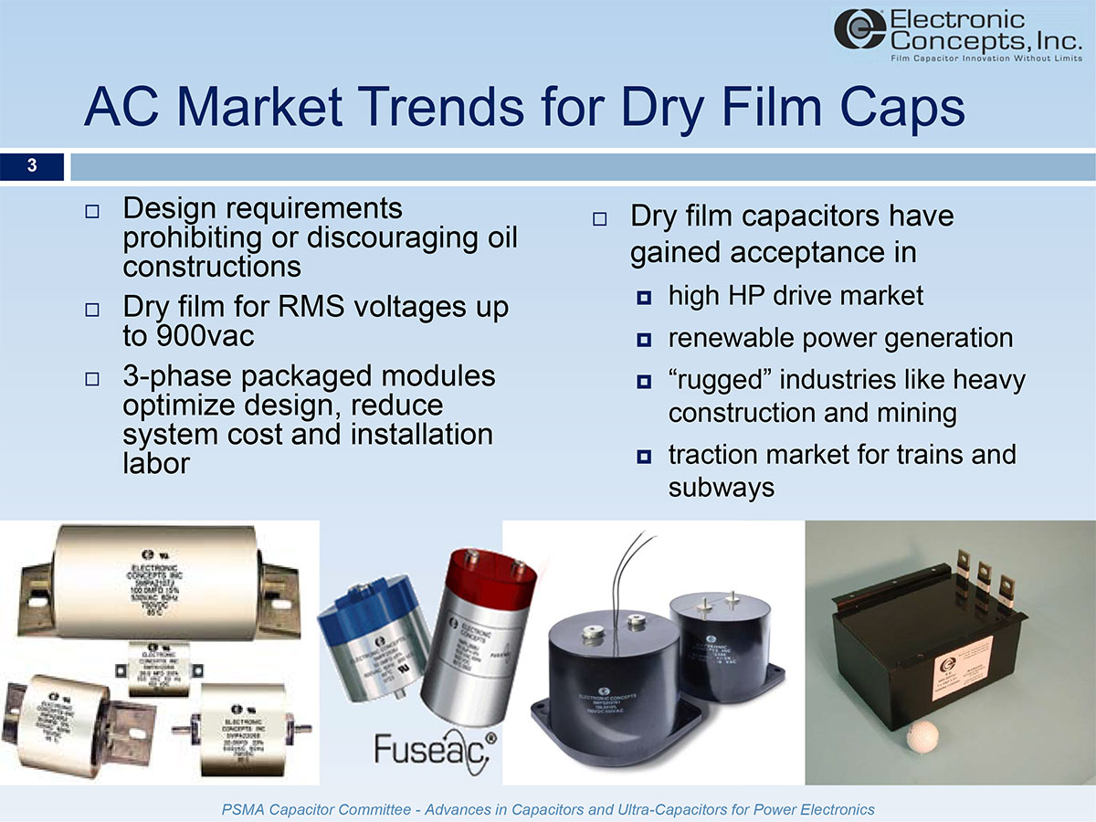
System designers have seen the introduction of regulations prohibiting or discouraging the use of oil filled capacitors over the last decade. The National Electric Safety Code (NESC) discourages use of oil filled capacitors through requirements only applicable if oil filled capacitors are used. Oil filled capacitors offer corona suppression, high transient voltage capability, good thermal transfer, and series disconnect safety mechanisms. Dry film capacitors can offer these advantages in light-weight designs filtering broader bandwidths of current spectrums without the risk of oil leakage and system contamination. These designs vary from discrete wrap and fill capacitors to units offering series disconnect or thermal feedback safety mechanisms. Modular designs provide packaged filters for three-phase filtering and can incorporate the safeties.
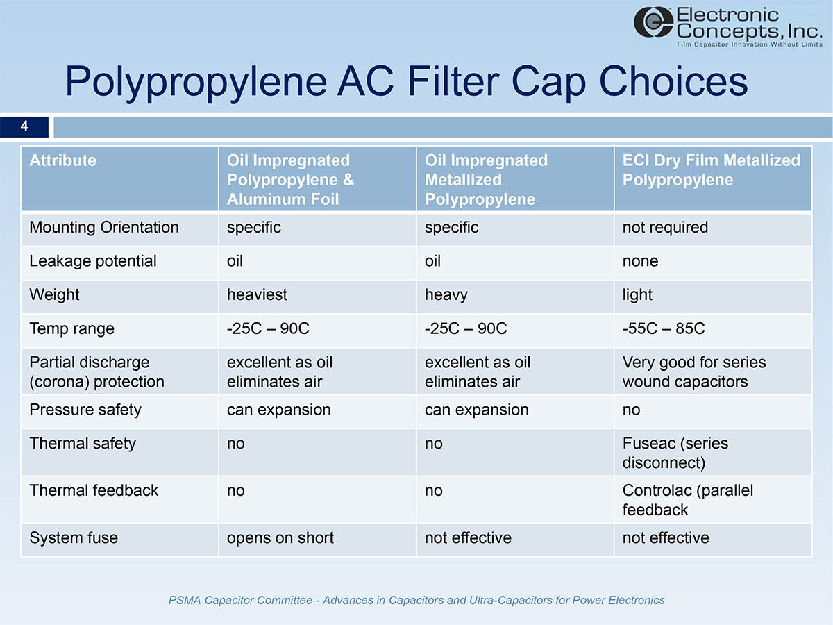
Polypropylene is used in oil filled and dry designs. Prop and aluminum oil filled designs are the largest and heaviest option but fail in a short that effectively opens system fuses in the event of capacitor failure. Metallized polypropylene designs employ a selfhealing mechanism advantageous to long life but do not fail dead short or open system fuses. Oil filled metallized polypropylene offers excellent corona suppression, but incorporates a function limiting safety such as a snap away conductor or pop top mechanism, both of which offer series disconnect protection if the capacitor fails. Dry film capacitors offer lighter designs and broad functionality, but until recently offered no safety mechanisms.

Dry construction metallized polypropylene capacitors use no oil or other liquids which may leak and contaminate systems. Because they are dry, there are no heavy cans with heavy ceramic terminals, no mounting orientation requirements, and may be packaged in many different sizes and configurations. The dry capacitors also use wide continuous conductors providing high RMS currents and large surface area for operation at higher frequency harmonics where skin-depth inhibits response. Polypropylene has very low losses over a wide frequency and temperature range. The capacitors can be specifically designed in filter modules fitting the electrical and mechanical system requirements. However, designers employing dry film capacitors need to understand how the capacitors are rated, the benefits of self-healing, and the failure modes possible without proper precaution.
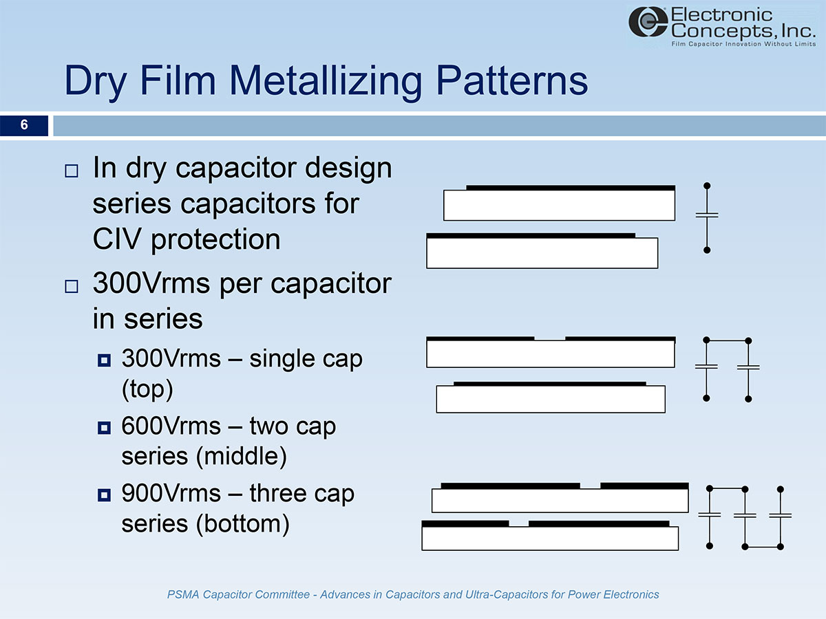
Oil filled capacitor suppress corona inception voltage (CIV) by replacing air in the capacitor with a vegetable oil. Corona partial discharges occur when ionization of air trapped in the margins of the windings begins to conduct for very short moments creating very high temperature arcing which vaporizes the electrode and degrades the polymer leading to premature failure. CIV testing of cylindrical capacitors wound on hard cores indicates sustainable pico-coulomb discharges begin approximately 350Vrms or higher in single cap designs. Conservatively a single cap winding is rated at 300Vrms maximum regardless of dielectric thickness that may support a higher peak voltage rating. For each increment of 300Vrms, another capacitor is added in series through the metallization pattern.
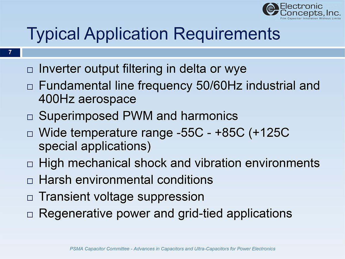
Industrial applications typically require a 50 or 60Hz fundamental AC. Aerospace applications often require 400Hz AC with much higher reactive power. ECI analyzes customer current spectrums combined with the fundamental frequency to assist engineers in selecting the proper capacitor for the application. Often the environments include a wide temperature range, high mechanical stress, and vibration, which may rupture seals in oil-filled units and contaminate the system. Regenerative power and grid-tied applications offer particularly stringent operation due to random voltage transients and line noise created as feedback during braking, or when multiple systems feed a grid without overvoltage protection such as MOV clamping or other transient voltage surge suppression (TVSS).
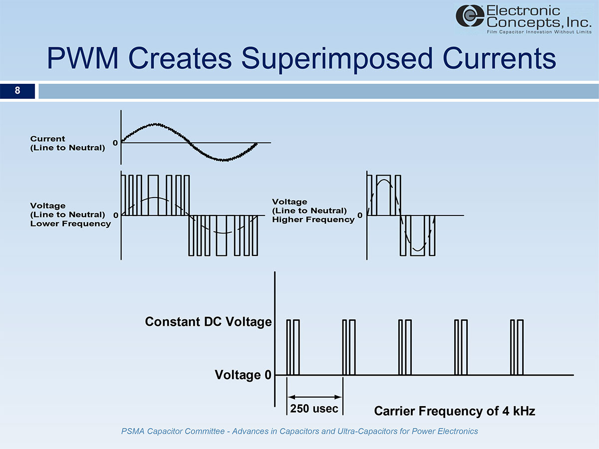
Pulse width modulation creates switching frequency currents and harmonics which superimpose on the fundamental AC frequency. The output filter capacitors must filter the entire spectrum from fundamental to harmonic frequencies. Metallized polypropylene has low loses across a wide bandwidth of frequencies making it the premier choice for filtering inverter outputs.
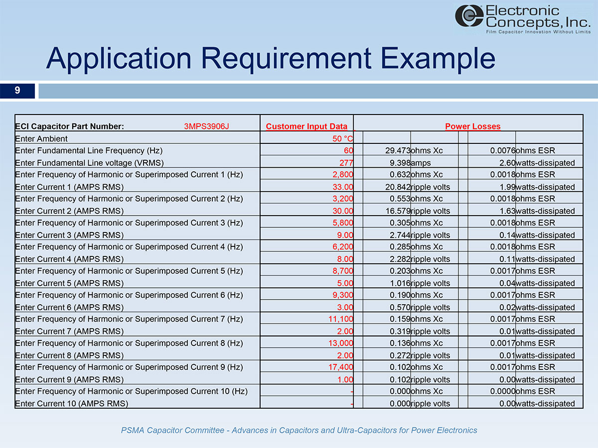
A typical application requirement includes the fundamental line frequency voltage resulting in a current relative to the capacitive reactance. Superimposed on the fundamental are various switch frequency harmonics. ECI analyzes the individual components of the current spectrum to determine the power dissipated as heating in the capacitor. Note that the ESR flattens quickly as the harmonic frequency increases. The larger the capacitance value, the lower the threshold frequency at which the ESR will essentially bottom out very close to the lowest ESR possible at the capacitor’s resonant frequency. For this reason, the fundamental line heating combined with heating from the RMS of the harmonics squared times a typical higher frequency ESR such as 10kHz, is often sufficient in comparison to the long method of individual frequency analysis.
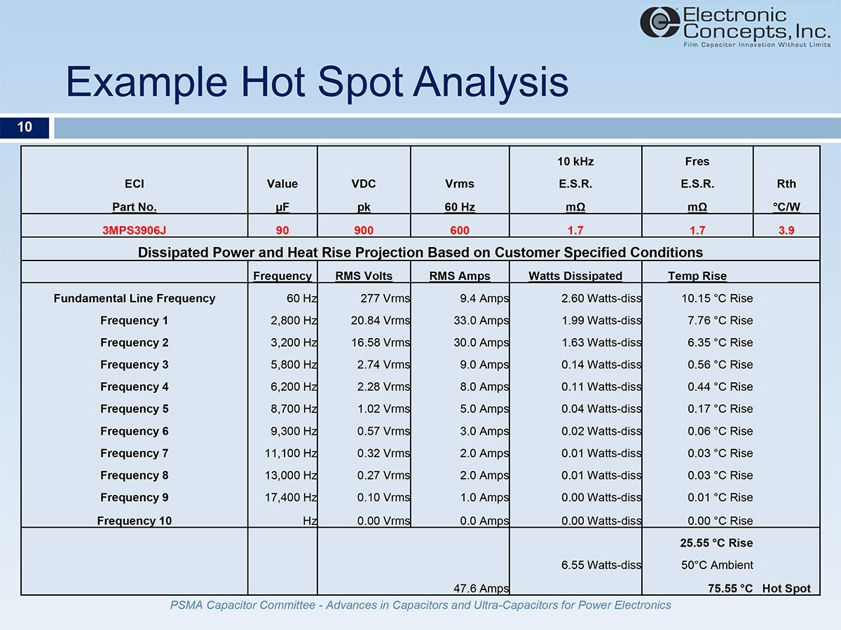
The output of the application analysis includes the power losses at each frequency and the heat rise at the capacitor hot spot due to the losses. By combining the internal heat rise and ambient temperature, the hot spot temperature is found. The hot spot temperature and voltage stress are then used to predict the capacitor operational life.
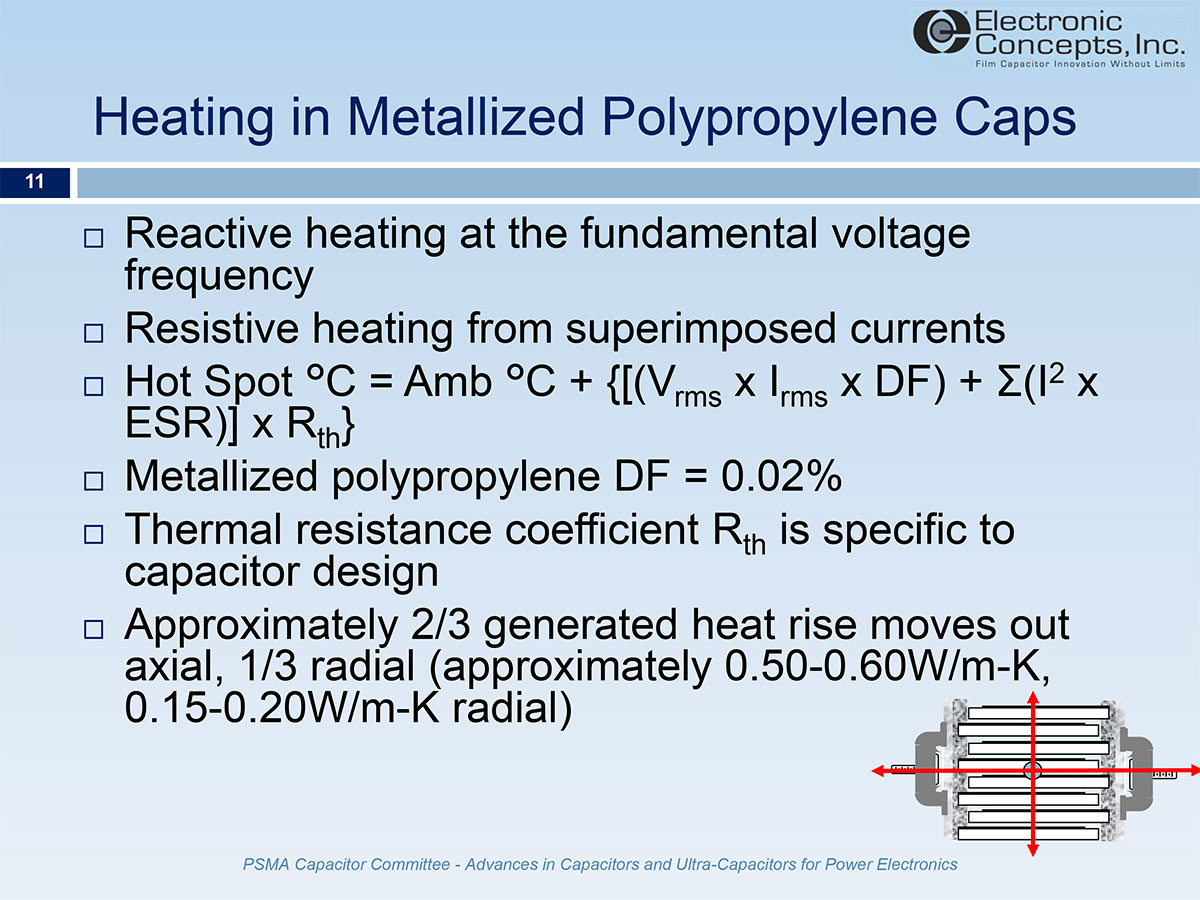
The heat rise realized in an application is a combination of the reactive heating at the fundamental frequency and the resistive heating due to the superimposed harmonic currents. The fundamental frequency losses are found from the applied power and the capacitor dissipation factor. The resistive heating is found as a function of I2ESR at each frequency. Thermal resistance is different for different capacitor geometries. Consider the geometries of a hockey puck and a soda can. The hockey puck has higher RMS current capability, lower ESR and ESL, and lower thermal resistance as a function of distance from the center to the end of the capacitor. The soda can has better volume efficiency as a function of fixed margins and offsets, but also higher ESR and ESL resulting in lower current potential and higher thermal resistance.
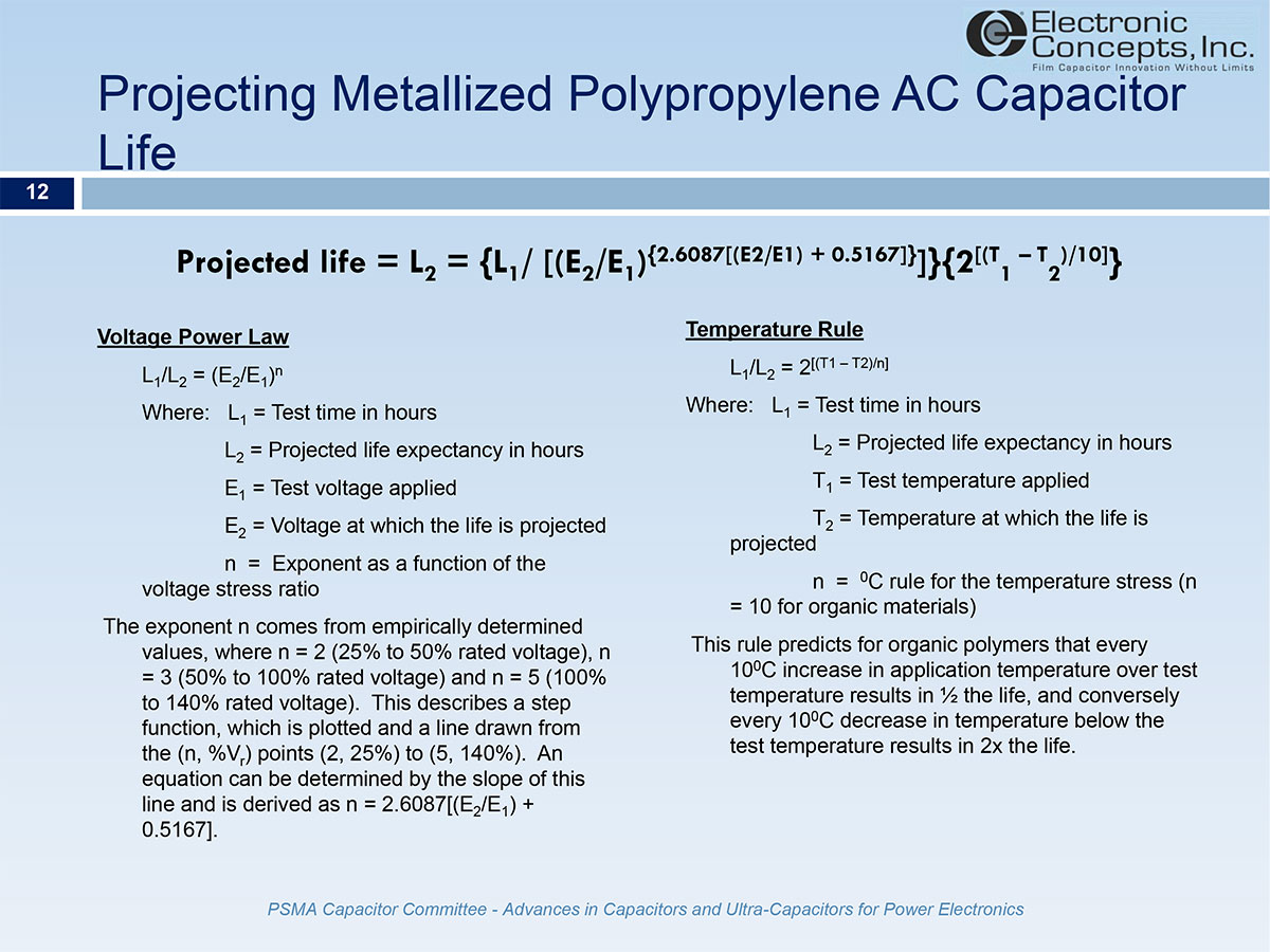
Life projection is a function of two factors, the Voltage Power Law and the 10C temperature rule. The Voltage Power Law examines the applied voltage as a ratio of the rated voltage based on a known test group. The lower the ratio the longer the life. The dielectrics are organic and follow the relationship for every 10C increase in temperature the aging reaction doubles resulting in half the life. The calculations for the life projections supplied are based on the work of John D. Moynihan as described in “Selection and Application of Capacitors”, Second Edition, Copyright 1987 by Components Technology Institute Inc.
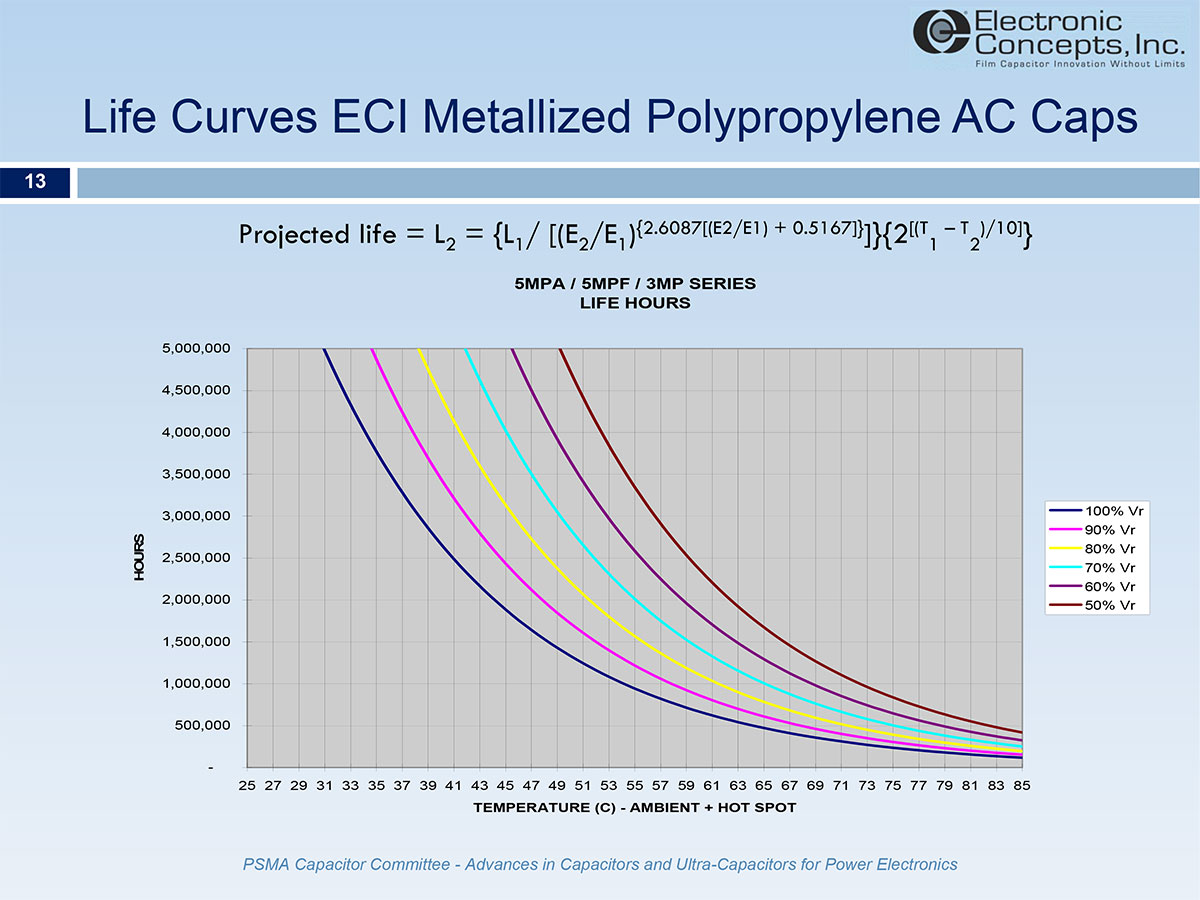
ECI metallized polypropylene AC capacitors share common life curves because they are designed on the same voltage stress criteria in volts per micron of dielectric thickness.
Capacitors fail through misapplication, extreme operating environments, and normal wear out. The system designer must take caution to employ best practices when selecting the capacitor. Often designers must rely on simulations to anticipate worst case conditions from operation, however predicting all possible scenarios in sophisticated applications such as multiple sources tied to a common grid is very difficult. Voltage transients are often culprits. High DV/DT realized during the first few nanoseconds of a ringing event (start, stop, fault…) often slowly degrade the capacitor until a threshold is passed in losses that leads to rapid failure. Discussing the application and providing as much information as possible during the capacitor selection phase is often essential to reliable long life operation.
Capacitors fail as a result of decreased capacitance in a normal wear out scenario. However initiating events can often lead to premature or catastrophic failure.
- High peak currents or DV/DT create partial discharges at the connections between the vapor deposited electrodes on the dielectric and the end spray connection used to connect the electrodes to the terminals.
- Overvoltage transients exceeding the peak voltage (or DC voltage) rating of the capacitor can produce excessive selfhealings. The byproducts of these self-healings include gases and carbon which increase leakage currents and loss factors.
- If ambient temperature and internal heat rise result in hot spot temperatures exceeding the temperature rating of the capacitor, voltage strength is compromised and dielectric breakdown leads to more self-healings.
- In an avalanching condition the capacitor continuously tries to self-heal which increases losses leading to higher temperature hot spot and more dielectric strength failure. This cycle can continue until thermal run-away occurs resulting in explosions (hermetically sealed units) and fires.
- Polypropylene melts approximately 160-170C and decomposes at approximately 325-350C. The byproducts of decomposition include combustible gasses.
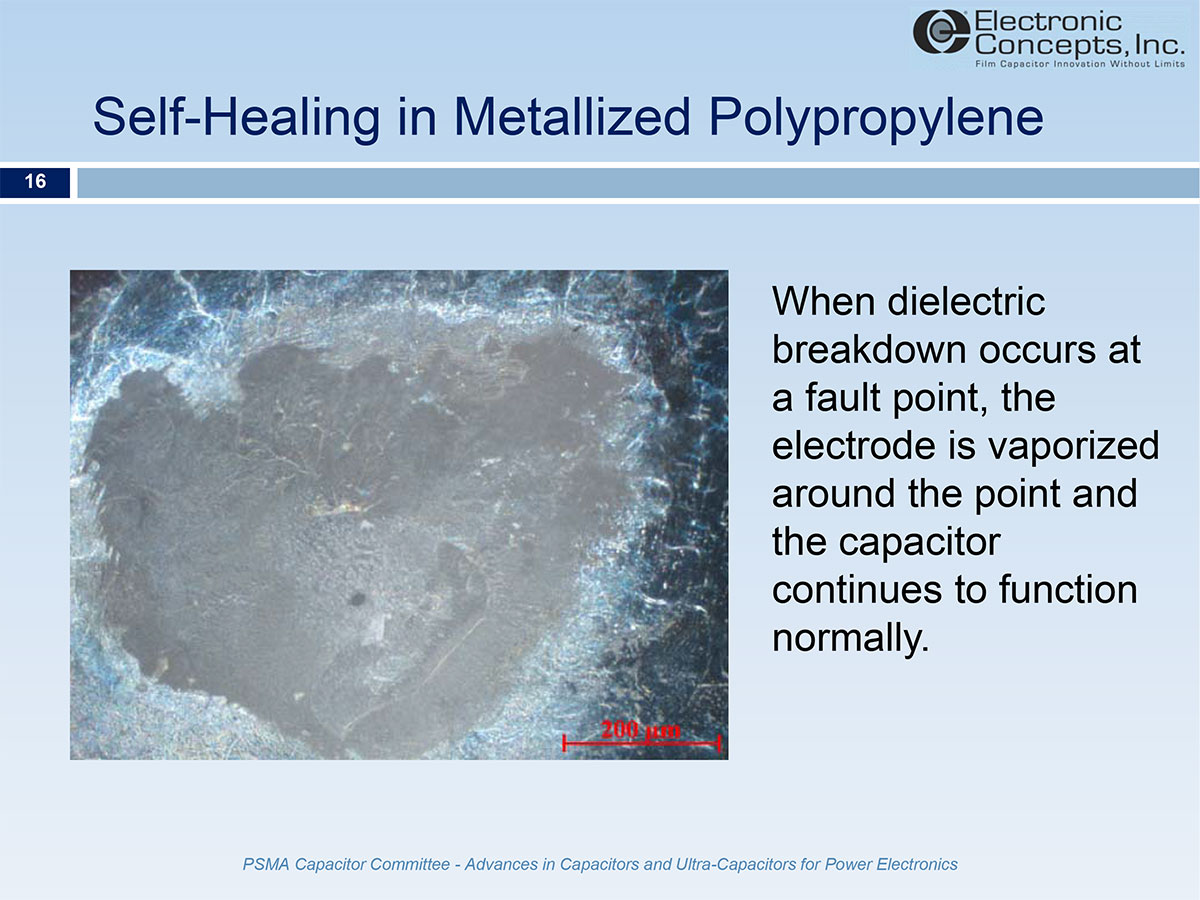
This picture shows a good clean self-healing. In the center a small hole is noted where breakdown originated at a fault point. The electrode around the hole is vaporized away in a radius around the hole relative to the applied voltage. The result is a clean selfhealing and continued normal functioning of the capacitor.
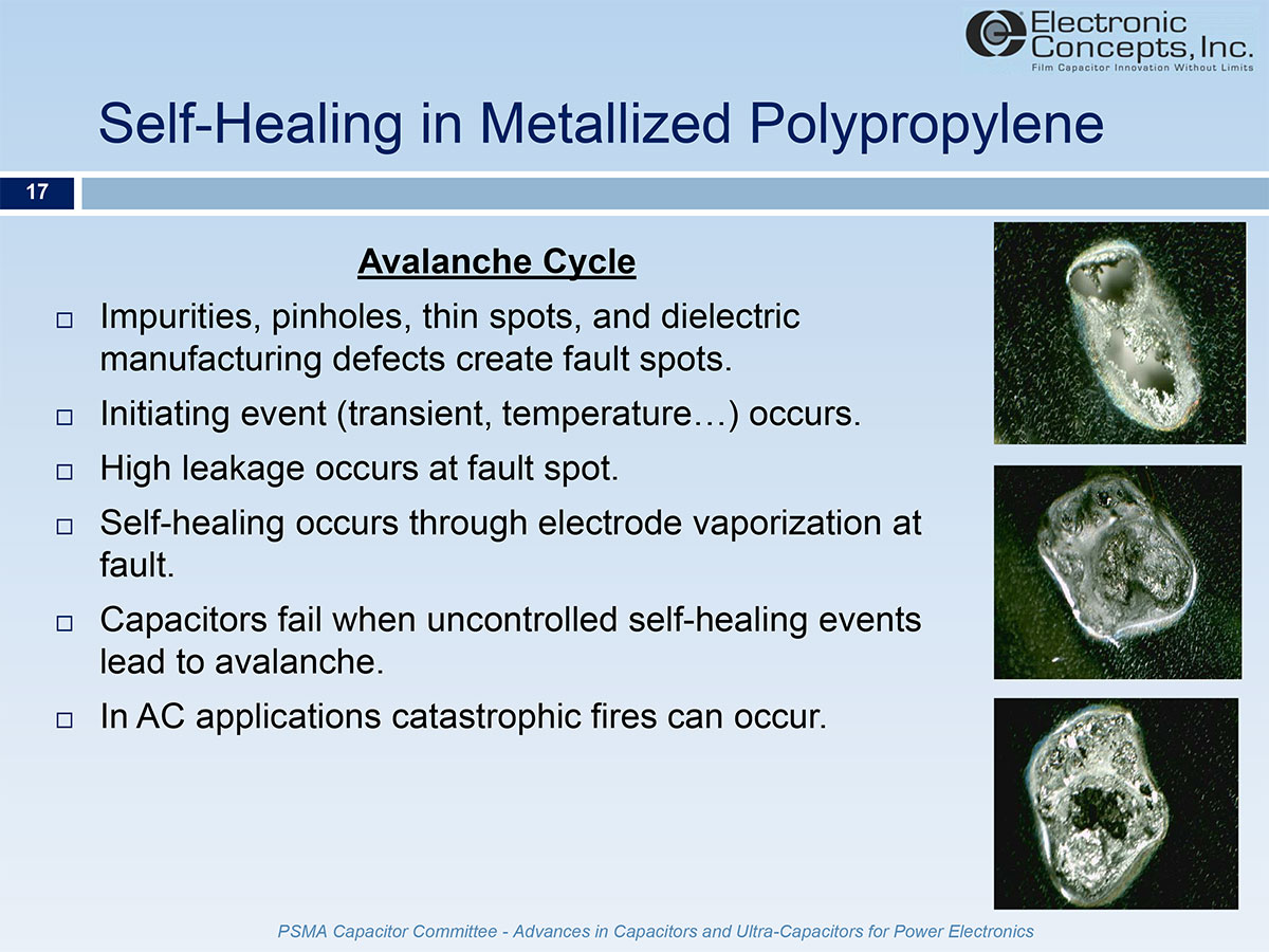
Some fault points however do not vaporize the electrode cleanly. High crystalline polypropylene is broadly accepted as the best choice for high reliability capacitors. The “ash content” refers to the inorganic byproducts residual in the polypropylene from the polymer reaction used to form the resin. These inorganic components do not vaporize during the clearing event of a selfhealing, and may persist to create new fault points. The temperature at a self-healing point is often thousands of degrees. In a normal clearing the event is very short duration and the mass of the capacitor quickly dissipates the temperature without further damage. However when a capacitor experiences clearings in a localized point, or excessive random clearings from over voltage breakdown, a residual heat builds until the dielectric begins to melt. As the dielectric melts the electrodes come in contact in much larger areas and the AC current continues to pump into the capacitor until the temperature rises to the point of decomposition.
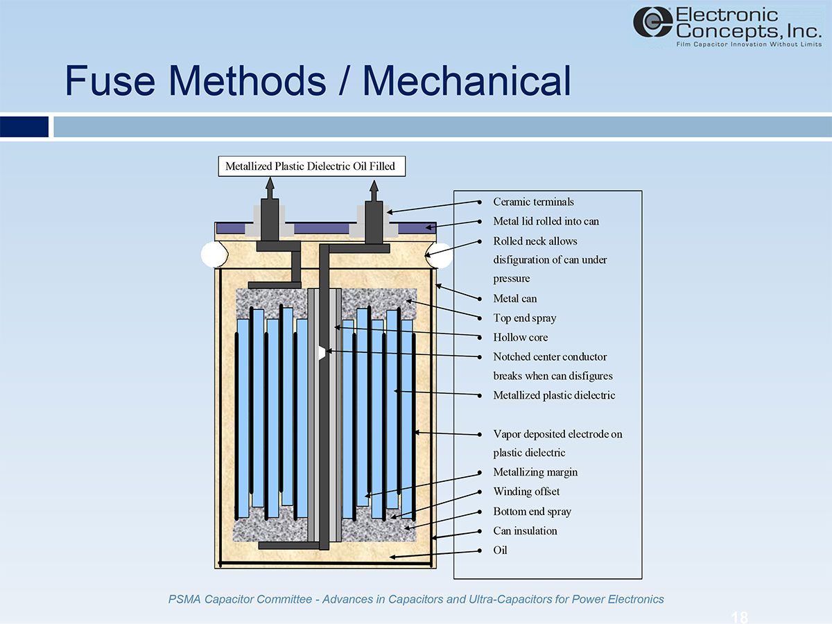
Oil filled capacitors depend on pressure generated by gas from self-healings to distort the can or lid and create the disconnect. To facilitate the mechanism, a notched conductor or mechanical contact is used. Installation of oil filled products must allow for can distortion. Rigid bus bars or other confining restraints of multiple capacitors across a rigid structure, may prevent the can from distorting and thus inhibit the series disconnect from functioning. Notched conductors affect ampacity and surface area for skin depth. Mechanical contacts are not continuous conductors and contact resistances and hot spots. Often oil capacitors emit audible noise between 500Hz and 20kHz due to mechanical vibration created by movement as polarity swings on the AC cycle.

ECI patented safety mechanisms include Fuseac, a series disconnect option, and Controlac, a parallel circuit feedback option.
Fuseac is a permanent disconnect. It consists of a full width conductor employing a specially designed joint at the hot spot of the capacitor, which reflows and opens at a threshold temperature between 95 and 105C. This method provides the full operational bandwidth of the unit without notched conductors or dry pressure contacts which compromise function and frequency bandwidth range.
Controlac is a parallel feedback which does not interrupt operation of the capacitor. The system employs a resettable thermal cut-out located at the hot spot of the capacitor. If the capacitor reaches 85C at the hot spot, the TCO opens. This method can be used to fire a relay coil and initiate a power down or alarm. It could also be used in series with a contactor coil to interrupt system power. The TCO resets when the temperature at the hot spot of the capacitor drops below 50C. Controlac allows system actions before the capacitor is destroyed or permanently disconnected. Diagnostics can be performed, or the capacitor removed for analysis and replaced with a new unit.
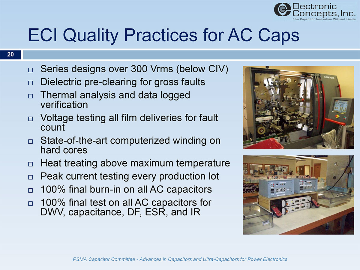
ECI uses several standards to ensure the highest quality capacitors. To prevent corona series designs are used based on 300Vrms maximum AC voltage per capacitor in series. Dielectric is specified with pre-clearing voltages to prevent gross faults from creating large self-healings in wound capacitors. Thermal analysis is used to test prototypes for harmonic currents using data loggers and implanted thermocouples. Incoming film deliveries are tested for maximum fault counts per specified area (different dielectrics use different stress factors). Sophisticated winding equipment controls tension throughout the winding process, and edge tracking ensures proper offset. Windings are made on hard cores to prevent loose turns at the start where partial discharges may occur in air gaps. All capacitors are put through a proprietary process of vacuum and temperature to stabilize windings above the operating and storage temperatures. Peak current testing on each lot secures the integrity of electrode to end spray connections. All AC capacitors are 100% burned-in at over voltage and elevated operating temperature. ECI performs 100% final testing for all critical parameters to ensure all delivered products meet the component specifications.
System designers making capacitor selections should employ sound practices to ensure reliable capacitor operation. This includes voltage and current de-rating, spacing around units for air flow, and proper mechanical mounting to prevent stress at electrical connections. Capacitors should be placed away from local heat sources. When building filter arrays, stress relief is needed to prevent inducing termination damage that leads to increased ESR and heating in the capacitor. Transient voltage suppression is critical when spurious voltage transients above rated voltage may feedback to the capacitor and the clamping voltage of the devices must be specified to the capacitor design engineer to ensure the DWV of the capacitor exceeds the clamping voltage of the surge protection. Monitoring cabinets for temperature or air flow ensures cooling fans are running and filters have not clogged. In large systems, fire alarms and power down sequences can prevent extensive system damage in the case of catastrophic failure.